Introduction
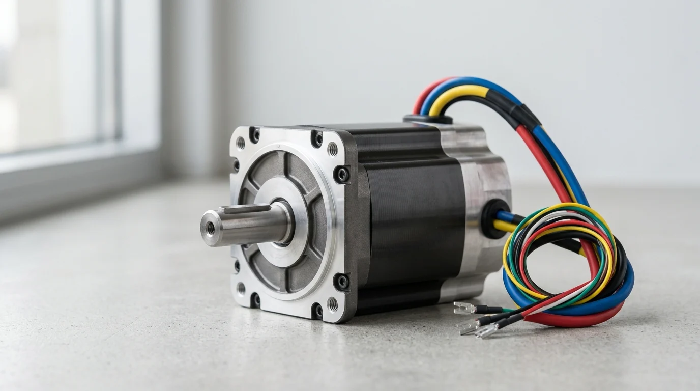
Choosing a BLDC motor for industrial equipment is a system-level decision, not a simple power match. Torque profile, duty cycle, thermal limits, speed range, enclosure needs, and drive compatibility all shape whether a motor will deliver reliable output or become a source of overheating, downtime, and early failure. This guide explains the core selection criteria engineers and buyers should evaluate, including continuous versus peak torque, operating environment, efficiency, bearing life, and control requirements. By the end, readers will have a practical framework for comparing motor options against real application demands and narrowing specifications before moving into detailed sizing and integration.
Why does BLDC motor selection matter for industrial performance
The specification of a brushless DC (BLDC) motor fundamentally dictates the mechanical output, energy consumption, and maintenance intervals of modern industrial machinery. Unlike their brushed counterparts, BLDC motors rely on electronic commutation, eliminating mechanical wear on brushes and allowing for operating efficiencies frequently ranging from 90% to 96%. This architectural shift drastically reduces thermal losses and extends the operational lifespan of the equipment.
However, industrial environments are unforgiving. Selecting the correct BLDC motor requires engineers to look beyond peak power ratings and evaluate the continuous thermodynamic and mechanical realities of the deployment environment. A mismatch between motor capabilities and industrial demands leads to premature stator insulation failure, demagnetization of the rotor, or drive faults.
How do application duty cycle, uptime targets, and operating conditions affect selection?
The duty cycle of an application is the primary determinant of continuous torque requirements. Motors subjected to an S1 continuous duty cycle must achieve thermal equilibrium without exceeding their insulation temperature limits. Conversely, intermittent duty cycles (such as S2 or S3) allow engineers to specify a smaller BLDC motor capable of delivering brief peak torque bursts—often 200% to 300% of the nominal continuous torque—provided the off-cycle allows sufficient cooling.
Uptime targets directly influence bearing selection and thermal overhead. For a manufacturing line requiring 99.9% uptime over a 10-year span, engineers must specify bearings with an L10 life exceeding 40,000 hours. Operating conditions further complicate selection; ambient temperatures fluctuating between -20°C and +85°C alter the internal resistance of copper windings and the flux density of the permanent magnets, requiring aggressive derating calculations to ensure reliable startup and continuous operation.
Which industrial use cases demand different BLDC motor trade-offs?
Different industrial sectors force engineers to prioritize distinct BLDC motor characteristics. In the material handling sector, Automated Guided Vehicles (AGVs) require compact, high-torque-density motors operating on 48V DC battery architectures. Here, the trade-off favors low-speed torque and physical compactness over maximum high-speed efficiency.
In contrast, industrial HVAC systems and fluid-handling pumps operate in steady-state conditions where energy consumption is the dominant total cost of ownership (TCO) factor. These applications demand BLDC motors optimized for peak efficiency at specific, continuous RPM bands, often operating directly from rectified AC mains at 310V DC. Aerospace and defense manufacturing use cases may prioritize extreme ingress protection and shock resistance over cost, highlighting how environmental and operational profiles force divergent engineering trade-offs.
Which BLDC motor specifications should industrial buyers evaluate first
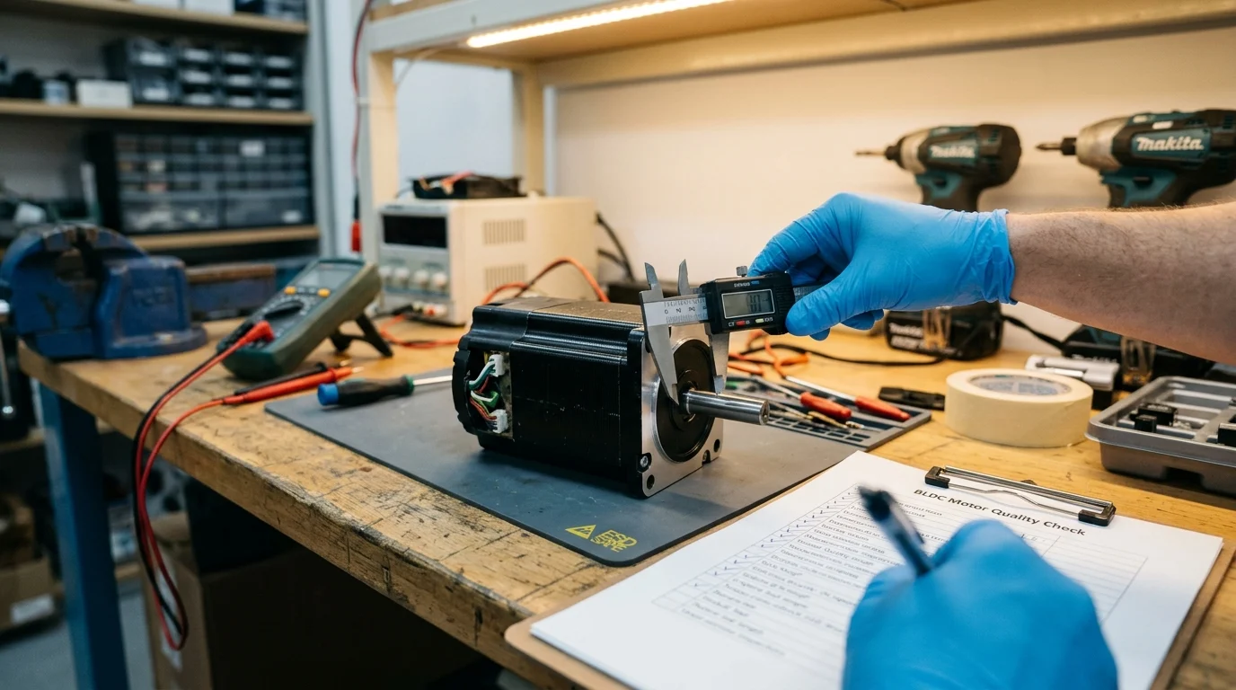
Evaluating a BLDC motor requires a systematic analysis of its electromechanical parameters. Industrial buyers must translate the mechanical load requirements into precise electrical specifications, ensuring the motor and its accompanying drive can operate synchronously without entering fault states.
How should speed, torque, power, voltage, and efficiency be compared?
Speed and torque are intrinsically linked in a BLDC motor, defined by the motor’s torque constant (Kt) and voltage constant (Kv). Engineers must map the application’s torque-speed curve against the motor’s capabilities, ensuring the continuous operating point falls well within the safe operating area. Power output is the product of speed and torque, but achieving that power requires specific voltage and current inputs.
Efficiency maps should be scrutinized not just at the rated peak, but at the actual anticipated operating load. Voltage selection is equally critical and often dictated by the available power infrastructure.
| Voltage Band | Typical Industrial Application | Key Advantage |
|---|---|---|
| 12V – 24V | Mobile robotics, small pumps | Operator safety, battery compatibility |
| 48V | AGVs, warehouse automation | Optimal balance of power density and safe voltage limits |
| 310V / 400V | Grid-tied HVAC, CNC spindles | Lowest current draw for high power output |
What do thermal class, ingress protection, insulation, and bearings indicate?
Thermal class determines the maximum allowable operating temperature of the motor’s internal winding insulation. Industrial applications typically demand Class F (155°C) or Class H (180°C) insulation to prevent short circuits under heavy continuous loads. Operating a motor just 10°C above its thermal rating can halve its operational lifespan.
Ingress Protection (IP) ratings dictate the motor’s resilience against environmental contaminants. An IP54 rating suffices for standard factory floors, but food processing and pharmaceutical environments require IP67 or IP69K ratings to withstand high-pressure, high-temperature washdowns. Furthermore, the mechanical bearings are often the first component to fail in a BLDC motor; specifying ABEC 5 or higher bearings with high-temperature synthetic grease is mandatory for high-radial-load applications.
Which BLDC motor and servo motor comparison points belong here?
While all servo motors are essentially highly refined BLDC (or AC synchronous) motors, not all BLDC motors are servos. The comparison hinges on inertia and feedback precision. A true servo motor is designed with a low-inertia rotor to allow for explosive acceleration and deceleration rates, often settling into position within milliseconds.
Additionally, servo motors integrate high-resolution absolute encoders (frequently offering 20-bit to 24-bit resolution) for exact positional control. Standard BLDC motors typically feature higher rotor inertia for smooth, continuous velocity and rely on simpler Hall-effect sensors or incremental encoders. Buyers must decide if the application genuinely requires micro-radian positional accuracy—which justifies the 200% to 400% cost premium of a servo system—or if stable velocity and directional control are sufficient.
How should engineers compare control architecture and integration
Because a BLDC motor lacks mechanical brushes, it relies entirely on an external electronic controller to sequence the phase currents. The architecture of this control system—specifically how the controller determines rotor position—dictates the motor’s low-speed performance, wiring complexity, and susceptibility to electrical noise.
When are sensorless and sensored BLDC motor designs the better choice?
Sensored BLDC designs typically utilize three Hall-effect sensors embedded in the stator, spaced at 120 electrical degrees. This configuration provides the drive with immediate, absolute rotor position data even at a standstill. Sensored designs are mandatory for applications requiring high starting torque under load, such as traction drives, robotic joints, and lifting mechanisms, where the motor must not stall or rotate backward upon startup.
Sensorless BLDC motors calculate rotor position by measuring the back-electromotive force (back-EMF) generated in the unenergized phase windings. Because back-EMF is proportional to speed, sensorless drives cannot accurately determine rotor position at zero or very low speeds. However, for continuous-velocity applications operating above 1,000 RPM—such as centrifugal pumps, compressors, and cooling fans—sensorless control removes the cost, wiring, and failure points of physical sensors, significantly increasing mean time between failures (MTBF).
How do driver compatibility, feedback options, and EMI performance affect integration?
The integration of a BLDC motor heavily depends on its compatibility with standard industrial drives. Engineers must match the motor’s inductance and resistance to the drive’s current loop tuning capabilities. Mismatched inductance can lead to aggressive current ripples, causing excessive motor heating and drive faults.
Electromagnetic interference (EMI) is another critical integration challenge. BLDC drives utilize pulse-width modulation (PWM) with switching frequencies typically ranging from 10 kHz to 20 kHz. The rapid rise times (dv/dt) of these pulses generate substantial radiated and conducted EMI. Mitigating this requires shielded motor cables, proper grounding techniques, and often the integration of inline chokes or ferrite beads to prevent the high-frequency noise from corrupting nearby sensor networks or programmable logic controllers (PLCs).
What commercial, compliance, and supply chain factors influence BLDC mot
Securing a high-performance BLDC motor on a datasheet is only half the engineering challenge; securing a reliable pipeline of those motors over a multi-year production run is equally critical. Supply chain volatility, regulatory compliance, and supplier quality controls can quickly derail an otherwise sound technical design.
How should buyers assess supplier quality systems, validation data, and lifecycle support?
Industrial buyers must rigorously audit a supplier’s Quality Management System (QMS). While ISO 9001 is a baseline, suppliers adhering to IATF 16949 (automotive standard) often provide superior lot-to-lot consistency and rigorous change-management protocols. Buyers should request Highly Accelerated Life Test (HALT) and Highly Accelerated Stress Screen (HASS) data to verify the motor’s theoretical MTBF against empirical destructive testing.
Lifecycle support is closely tied to Minimum Order Quantity (MOQ) thresholds. While standard off-the-shelf motors might have an MOQ of 1 to 50 units, custom-wound stators or modified shafts frequently trigger MOQs of 500 to 1,000 units. Buyers must align their production forecasts with the supplier’s volume requirements to avoid excessive inventory holding costs or sudden supply interruptions.
Which compliance, safety, documentation, lead time, and lifecycle risks matter most?
Regulatory compliance is a strict barrier to market entry. Motors intended for the European market must carry CE marking and comply with the RoHS directive, while North American deployments typically require UL 1004-1 recognition for rotating electrical machines. Failure to source pre-certified motors can add tens of thousands of dollars and months of delay to system-level certifications.
Lead times represent the most immediate supply chain risk. The global procurement of rare-earth neodymium magnets and electrical steel can cause extreme lead time fluctuations.
| Sourcing Variable | Standard COTS Motor | Custom Wound / Modified Motor |
|---|---|---|
| Typical Lead Time | 4 to 8 weeks | 16 to 24 weeks |
| Minimum Order Qty (MOQ) | 1 to 50 units | 500 to 2,000+ units |
| Unit Cost (at volume) | Baseline | 10% to 30% premium |
| Engineering NRE | None | $5,000 to $25,000+ |

Translating a complex industrial application into a finalized BLDC motor purchase order requires a disciplined, iterative workflow. Ad-hoc selection often results in over-specification—driving up costs unnecessarily—or under-specification, leading to catastrophic field failures.
Which step-by-step selection workflow helps convert application needs into requirements?
The selection workflow must begin with the mechanical load profile. Engineers should calculate the root mean square (RMS) continuous torque to determine the motor’s thermal sizing, followed by the peak torque required for acceleration and overcoming static friction. Step two involves defining the environmental envelope: ambient temperature limits, required IP rating, and shock/vibration parameters.
Step three maps the electrical constraints. Engineers must verify the available DC bus voltage and the maximum allowable current draw, ensuring the motor’s Kt and Kv parameters align with these limits. Finally, step four defines the control and feedback architecture, selecting between sensored, sensorless, or high-resolution encoder feedback based on the required velocity precision and low-speed torque demands.
How should decision makers balance performance, reliability, cost, and availability?
Decision makers are ultimately tasked with optimizing the Total Cost of Ownership (TCO) over a typical 5-to-10-year industrial lifecycle. Specifying a motor with premium neodymium magnets and ultra-low-loss laminations may introduce a 20% to 30% upfront cost premium. However, if that motor operates a continuous 24/7 pump, the resulting 3% gain in electrical efficiency can recover the initial cost difference within the first 18 months of operation.
Conversely, for intermittent-duty applications like automated actuators, prioritizing immediate availability and lower upfront costs over peak efficiency is often the superior commercial strategy. By standardizing the evaluation of thermal limits, control integration, and supply chain realities, engineering teams can confidently secure BLDC motors that deliver both immediate performance and long-term industrial reliability.
Key Takeaways
- The most important conclusions and rationale for BLDC motor
- Specs, compliance, and risk checks worth validating before you commit
- Practical next steps and caveats readers can apply immediately
Frequently Asked Questions
What is the first factor to check when selecting a BLDC motor for industrial use?
Start with the load’s continuous torque and speed at real duty cycle. Then confirm voltage, thermal class, and efficiency at the actual operating point, not just peak ratings.
How does duty cycle affect BLDC motor sizing?
S1 continuous duty needs a motor that can hold torque without overheating. Intermittent S2/S3 duty may allow a smaller motor if cooling time between peak loads is sufficient.
Which BLDC voltage range is best for pumps, fans, or HVAC systems?
Small mobile equipment often uses 12–48V. Industrial fans, pumps, and HVAC commonly favor higher DC bus levels like 310V for lower current and better efficiency.
Why are thermal class and IP rating important in industrial BLDC motors?
They show whether the motor can survive heat, dust, and moisture. For demanding sites, Class F or H insulation and an application-appropriate IP rating help prevent early failure.